
| Version 2 (modified by , 18 years ago) ( diff ) |
|---|
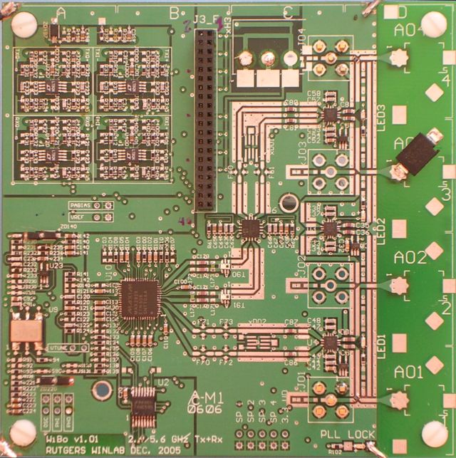
Orbit Noise Generator Wireless Board (WiBo)
WiBo102 is a 4.00 x 4.00” printed circuit board (PCB) designed around a Maxim, Inc. MAX2829ETN+D radio transceiver chip. This chip incorporates most of the radio functions except for the reference oscillator, baseband I/Q amps, power amps and antenna switches.
Four antennas (A01-A04) are mounted directly to WiBo102 though provision is made for adding SMA connectors and using off-board antennas if necessary. Two antennas are primarily for transmission (Tx) and two for receiving (Rx). Antenna switching is possible for diversity gain. It is also possible to switch all Tx and Rx signals into a single antenna.
- PCB
The PCB is a 4.00 x 4.00” FR-4 four-layer controlled impedance stackup board manufactured by Advanced Circuits, Inc.(http://www.4pcb.com/index.htm). For orientation purposes, reference marks are shown along the top (A-D) and right sides (1-4) of the board in one inch increments.
Looking from the top down, the top copper layer is the component side with all the high-frequency RF transmission lines. The dielectric under this layer is 20 mils thick. The structure of the traces is coplanar waveguide with ground (CPWG). A trace width of 30 mils and gap-to-ground of 18 mils provides a very close match to a 50ohm characteristic impedance.
The next copper layer down is all ground plane. The third layer down is a signal layer with predominately vertical traces surrounded by ground plane. The fourth or bottom layer is another signal layer with predominately horizontal traces.
Attachments (7)
- WiBo-103-Schematics.pdf (1.7 MB ) - added by 18 years ago.
-
MAX2828-9ds.pdf
(1.0 MB
) - added by 18 years ago.
Maxim Datasheet - UNDER NDA — NOT FOR DISTRIBUTION OUTSIDE WINLAB —
- MM74HC595.pdf (118.7 KB ) - added by 18 years ago.
- lt1994.pdf (288.1 KB ) - added by 18 years ago.
- uPG2035.pdf (148.2 KB ) - added by 18 years ago.
- AWL6951.pdf (671.0 KB ) - added by 18 years ago.
- WiBo-Photo.jpg (148.2 KB ) - added by 18 years ago.