
| Version 10 (modified by , 13 years ago) ( diff ) |
|---|
Table of Contents
Hardware Description
The new chassis manager uses a completely new set of hardware compared to the older revisions. The design is based around the Lantronix XPort AR module, along with accompanying external hardware for interface to the node. The SDK for this device allows the implementation of custom code which is used to interface and understand CMC instructions.
Major Hardware Components
Lantronix XPort AR
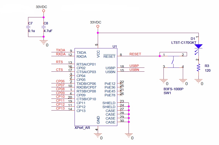
The Xport AR is an embedded device server, produced by Lantronix. It runs off of the Evolution OS®, combined with the custom software written using the Xport AR SDK. The Xport AR acts as the 'brains' of the CM3, handling all the networking tasks, as well the link between the CMC instruction commands, and the physical interface to the node. It has the following basic features:
| Architecture | |
| CPU | Based on the DSTni-EX enhanced 16-bit, 120MHz x86 Architecture |
| Memory | 1.25 MB RAM and 4 MB FLASH |
| Firmware | upgradeable via FTP,TFTP, Serial Ports, Internal Web Server |
| Diagnostics | Built in diagnostics and comprehensive statistics |
| Network Interface | |
| Interface | Ethernet 10Base-T or 100Base-TX (Auto-Sensing) |
| Connector | RJ45 |
| Layer 3 Protocols | TCP, UDP, IP, ARP, ICMP, SSH, SSL, XML, HTTP, PPP, PAP, CHAP, DNS, SMTP, RSS, DHCP, BOOTP, AutoIP, SNMP, FTP, TFTP, Telnet, CGI |
| Serial Interface | |
| Interface | CMOS (Asynchronous, 5V Tolerant) |
| Data Rates | 300 bps to 230,400 bps (selectable by 1bps increments) |
| Characters | 7 or 8 data bits |
| Parity | Odd, even, none |
| Stop Bits | 1 or 2 |
| Control Signals | RTS, CTS, DSR, any PIO |
| Flow Control | XON/XOFF, RTS/CTS, User Selectable Characters |
The GPIOs are used to control the solid state relays used to power the node on/off and reset the node, as well as monitor the 'hardware status', see the next section for details on this.
More information on the Xport AR can be found here
Voltage Monitor
The CM3 has a PC voltage monitoring chip installed, the
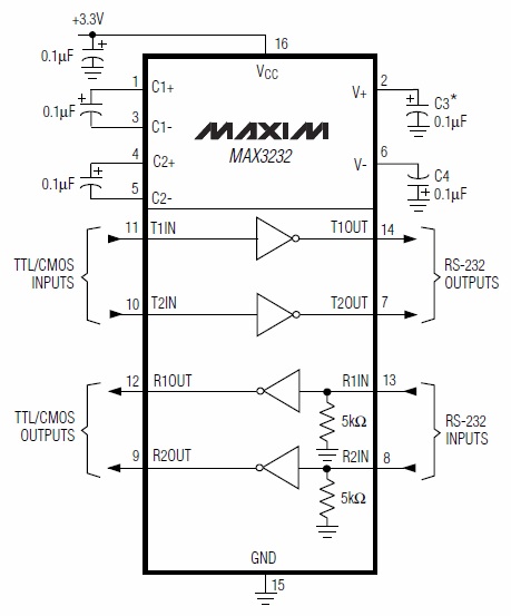
RS232 Level Shifter
Solid State Relays
Attachments (9)
-
SCHEMATIC1 _ Xport.pdf
(25.2 KB
) - added by 13 years ago.
Schematic of CM3
-
CM_232.jpg
(57.3 KB
) - added by 13 years ago.
RS232 Level shifter (schematic)
-
CM_232_2.jpg
(51.6 KB
) - added by 13 years ago.
RS232 Connections (schematic)
-
CM_Relay.jpg
(34.3 KB
) - added by 13 years ago.
Solid State Relays (schematic)
-
CM_Monitor.jpg
(75.1 KB
) - added by 13 years ago.
Hardware Monitor (schematic)
-
CM_Xport.jpg
(87.8 KB
) - added by 13 years ago.
Xport AR (schematic)
-
xport_ar.jpg
(6.7 KB
) - added by 13 years ago.
Xport AR (image)
-
DS1780E.gif
(21.2 KB
) - added by 13 years ago.
Hardware Monitor (block diagram)
-
CM_232_block.jpg
(51.4 KB
) - added by 13 years ago.
RS232 Level shifter (block diagram)
Download all attachments as: .zip