
| Version 5 (modified by , 14 years ago) ( diff ) |
|---|
Custom Riser Card for MB770 Platform
MB770 motherboard is only PCI 2.1 compliant and therefore doesn't provide 3.3VSB (3.3 V stand-by voltage) on pin A14 of the PCI bus connector. This voltage is is supplied to the core of CM2 and is used to turn the main power on/off. Furthermore, even the wake-on LAN (WOL) connector on the motherboard doesn't provide stand-by voltage (and on most motherboards the WOL connector is not even installed).

One solution to this problem was to create a custom riser card shown in figure 1 which has a separate feed for stand-by voltage directly from the power supply, voltage regulator for 5 to 3.3 V conversion and feeds 3.3V to the CM2 card on PCI connector A14.
Standby voltage feed
 CM2 stand-by voltage is provided with the separate wire that is attached directly to the +5VSB wire of the ATX power supply with the self-tapping connector (MOLEX Multi-Lock Insulation Displacement Connector (IDC) ) show on figure 2.
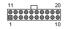
The purple wire on the ATX power supply connector is fed through the slit opening on the IDC while the red wire from the riser card is fed into the second hole on the clip and the taping header is gently squeezed into position and locked with the cover  Connector Pin Layout")
| Pin | Name | Color | Description | |
|---|---|---|---|---|
| 1 | 3.3V | Orange | +3.3 VDC | |
| 2 | 3.3V | Orange | +3.3 VDC | |
| 3 | COM | Black | Ground | |
| 4 | 5V | Red | +5 VDC | |
| 5 | COM | Black | Ground | |
| 6 | 5V | Red | +5 VDC | |
| 7 | COM | Black | Ground | |
| 8 | PWR_OK | Gray | Power Ok (+5V & +3.3V is ok) | |
| 9 | 5VSB | Purple | +5 VDC Standby Voltage (max 10mA) | |
| 10 | 12V | Yellow | +12 VDC | |
| 11 | 3.3V | Orange | +3.3 VDC | |
| 12 | -12V | Blue | -12 VDC | |
| 13 | COM | Black | Ground | |
| 14 | /PS_ON | Green | Power Supply On (active low) | |
| 15 | COM | Black | Ground | |
| 16 | COM | Black | Ground | |
| 17 | COM | Black | Ground | |
| 18 | -5V | White | -5 VDC | |
| 19 | 5V | Red | +5 VDC | |
| 20 | 5V | Red | +5 VDC |
Installation
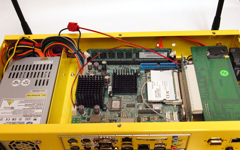
The assembled node with custom raiser and CM2 card is shown in Figure 3. The +5VSB clamp and feeder wire are pulled out of the box just to emphasize the setup.
 with custom riser card and CM2 installed")
Attachments (4)
-
CM2-Riser.jpg
(31.1 KB
) - added by 16 years ago.
Custom CM2 Riser Card
-
Node-with-CM2.jpg
(136.8 KB
) - added by 16 years ago.
ORBIT node (V2) with custom riser card and CM2 installed
-
Clip.jpg
(37.0 KB
) - added by 16 years ago.
Self-tapping connector
-
ATX20-Male.png
(579 bytes
) - added by 16 years ago.
ATX-20 Pin Male (cable) Connector Pin Layout
Download all attachments as: .zip